Normalisation Calibration#
The goal of Normalisation Calibration#
The goal of Normalisation Calibration enable a correction for the wavelength response of the instrument when conducting data reduction. This is done by generating a normalisation correction file and additional parameters that govern how it is applied.
As with other SNAPRed operations, the generated normalisation data are state specific and respect the `isLite setting. Correspondingly, for each state, the normalisation workflow must be executed separately for normal and lite outputs in order to subsequently reduce both modes of SNAP data.
Inputs#
The main input to normalisation are two experimentally measured datasets: one from a sample of either vanadium or vanadium-niobium and a corresponding empty instrument measurement. It is mandatory that these datasets are collected in the same instrument state. These are specified via their run numbers.
Geometric and neutronic information on the calibrant material, specified via selection of a corresponing calibrant file in
jsonformat.
Overall methodology#
In SNAPRed the generation of a normalisation correction proceeds in two distinct stages. The first of these occurs prior to any diffraction focusing while the second state occurs post diffraction focusing. The reasons for dividing up the normalisation correction in this way are three fold:
Performance The input vanadium datasets tend to be very large and are costly to load. Furthermore, the absorption corrections that are applied prior to diffraction focusing are also computationally expensive. Doing these calculations upfront and applying appropriate management of the events in the final saved file greatly reduces the subsequent execution time for subsequent sample data reduction
Arbitrary grouping A design principle of
SNAPRedis that it facilitates the application of multiple pixel grouping schema during reduction. By diffraction focusing the vanadium correction during reduction, it is ensured that the same grouping schema is applied to both sample data and normalisation correctionPixel masking An important feature of certain measurements on SNAP are pixel masks that can vary even from run-to-run. It is essential that these masks are also applied to the normalisation data prior to diffraction focusing. Retaining a cached, unfocussed normalisation correction enables this.
In light of this approach, the workflow for Normalisation Calibration includes the generation of the unfocussed normalisation correction (also called a “raw vanadium” in SNAPRed parlance) and the derivation of parameters - relating to peak stripping and smoothing - that will subsequently be used during data reduction when the final focused normalisation correction is generated and applied. In order to enable the latter, the normalisation calibration workflow includes a diffraction focussing step to allow assessment of the result.
The unfocussed correction (generating a “raw vanadium”)#
The generation of the raw vanadium begins with loading the experimental vanadium data (V-Nb alloy is also used) and a corresponding background measurement. It is (of course) mandatory that these are from the same isntrument state. The latter is subtracted from the former to remove instrumental background that does not represent beam scattered from the sample. The residual events are transformed into wavelength space and an absorption correction calculated. Currently SNAPRed can run this calculation for either cylindrical or spherical calibrants, and calls mantid algorithms SphericalAbsorption or CylinderAbsorption respectively.
Note
As described in the mantid documentation a large number of different absorption corrections are supported. At present, SNAPRed uses the base class absorption correction that uses a calculation of a mesh of a given element size.
These absorption corrections require inputs that describe the geometry, material, crystallographic and nuclear properties of the calibrant material. Each available calibrant has its own unique json file specifying these properties.
Finally, the absorption-corrected raw vanadium correction data are converted to TOF and lorgaithmically rebinned, using a binning parameter that matches the smallest found in the list of grouping schemes specified for the state.
Note
At present, the raw vanadium correction data are retained as event data and can often get very large. The intention is to either histogram these data or to retain, but compress, events, but this is not yet implemented. Compressed/Histogrammed datasets, in Lite mode will never exceed ~ 1 Gb in contrast with event datasets that can exceed ~30 Gb.
Inspecting the vanadium correction and optimising peak removal and smoothing#
Although it is the unfocussed raw vanadium that’s persisted to disk, this dataset still contains measurement artifacts (principally experimental noise and, in the case of vanadium, coherent Bragg peaks). For reasons described above, these are managed during data reduction, however, it remains important to inspect these under the conditions that they will be applied. Moreover, the smoothing parameters that will be used during data reduction must be determined at this point. To enable this, the normalisation calibration workflow includes a step where the raw vanadium is focused.
The user is able to visualise the diffraction-focused vanadium correction, as a function of d-spacing, and may select any defined pixel grouping scheme for the relevant instrument state to do this (see Figure). The choice of d-spacing units allows inspection and removal of any calibrant Bragg peaks. In SNAPRed peak removal and smoothing are done in a single operation. This is achieved by defining the extent of any present Bragg peak and ignoring data in this range when fitting a spline. Correspondingly, the first step in the workflow should be to ensure that peak extents are correctly specified. The location and width of Bragg peaks are automatically calculated, however, the user has two ways to exclude peaks. Firstly, they can use the dMin and dMax parameters to limit the d-range over which Bragg peaks are allowed (n.b. this does not affect the d-range of the vanadium correction itself). Secondly, they can adjust the intensity threshold to exclude weak peaks.
Once peaks are correctly marked, then the user should use the smoothing slider to set an appropriate level of smoothing. This level should capture real structure in focused vanadium (that may be caused, for example, by Bragg edges in the upstream vacuum windows), but should remove very high frequency noise in the data. This process is not currently automated, as the corresponding smoothing parameter is affected by data count time and binning, but may be automatable in the future. A plot of the residual and a calculated \(\chi^2\) between original and smoothed data would also be helpful but isn’t yet provided.
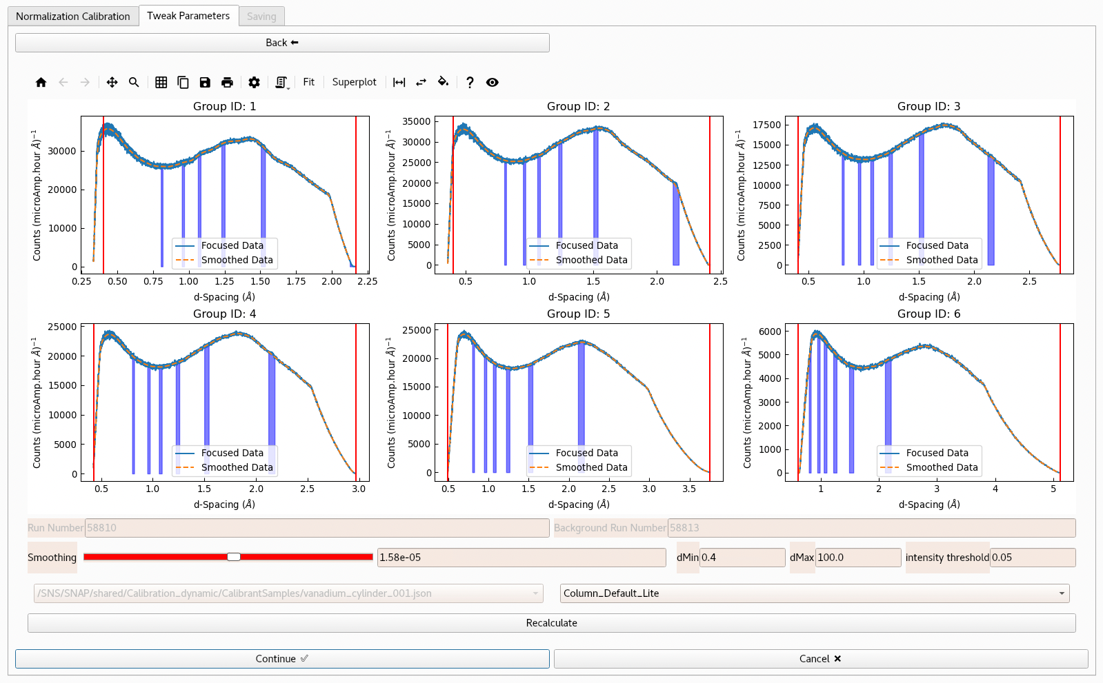
Fig. 4 Diffraction focused vanadium data for each pixel group within the chosen scheme are shown on a grid (with group ID increasing from top to bottom, left to right). Passing through the data is the smoothed and peak-stripped correction itself, shown as a dashed orange line. The regions corresponding to the expected Bragg peaks are shown as purple areas underneath the data at the calculated location of peaks. The level of fidelity with which the smoothed curve fits the data can be adjusted using the Smoothing slider. The list of peaks to be stripped can be controlled with the parameters dMin, dMax and Intensity Threshold.#
Note
Particular care should be taken to inspect the smoothed output at the ends of the spectra and in regions, which can be created by certain pixel grouping schemes, where there are sharp inflections in the measured data.
Workflow completion#
After the vanadium correction has been generated, the final raw vanadium is persisted to disk in the corresponding state calibration folder, from where it will be later extracted during sample data reduction. In addition, a normalisation record is saved that includes all of the parameters specified to generate the corresponding raw vanadium and the smoothing parameters used during inspection.